WRF code Optimisation for Meso-scale Process Studies (WOMPS) dCSE Project Report
A. R. Porter and M. Ashworth, |
This document is the final report for the DCSE-funded project to optimise the performance of the Weather Research and Forecast model (WRF) on the Cray XT4 component of HECToR.
The WRF model was developed as a collaborative project by the National Center for Atmospheric Research (NCAR), the National Oceanic and Atmospheric Administration (NOAA), the National Centers for Environmental Prediction, the Air Force Weather Agency, the Naval Research Laboratory, the University of Oklahoma and the Federal Aviation Administration in the United States. It is a regional- to global-scale model intended for both research applications and operational weather-forecast systems.
WRF is now used as the NOAA’s primary forecast model, for forecasts of 1–3 days ahead, and is used by weather agencies all over the world (including weather agencies in Indo-China and Asia). As of June 2008 there were in excess of 6000 registered WRF users.
The WRF system incorporates two different dynamics solvers; the Advanced Research WRF (ARW) solver (developed by the Mesoscale and Microscale Meteorology Division of NCAR) and the Non-hydrostatic Mesoscale Model solver (developed by the National Centers for Environmental Prediction, US). In this document we will discuss only the ARW version of the WRF modeling system.
The ARW solves the fully-compressible, non-hydrostatic Euler equations using a finite-difference scheme on an Arakawa C-grid staggering in the horizontal plane and a terrain-following, dry hydrostatic pressure vertical coordinate. There are 2nd- to 6th-order advection options for spatial discretization in both horizontal and vertical directions. Integration in time is performed using a time-split method with a 2nd- or 3rd-order Runge-Kutta scheme with a smaller time step for acoustic- and gravity-wave modes. The model supports periodic, open, symmetric and specified lateral boundary conditions and is capable of whole-globe simulations using polar Fourier filtering and periodic east-west boundary conditions.
The WRF model has, from the outset, been designed and written to perform well on massively-parallel computers. It is written in Fortran90 and can be built in serial, parallel (MPI) and mixed-mode (OpenMP and MPI) forms, simply by choosing the appropriate option during the configure process.
Unless stated otherwise, all results presented here were obtained with version 3.1.1 of WRF using the ARW core.
The bulk of this work was performed on HECToR which is the current incarnation of the UK’s national academic supercomputing service. When this project began, the scalar component of HECToR was at Phase I with each ‘node’ of the Cray XT4 comprising a single, dual-core AMD Opteron 2.8 GHz chip. However, HECToR was upgraded to Phase IIa in 2009 and now each node comprises a single, quad-core AMD Opteron 2.3GHz Barcelona chip. (The node interconnect is unchanged from Phase I).
Unless stated otherwise, all results are from Phase IIa of the HECToR Cray XT.
For the investigation of multi-core effects we have also made use of Monte Rosa which is a Cray XT5 at the Swiss National Supercomputing centre (CSCS). Rosa has compute nodes built from two, six-core AMD Opteron 2.4 GHz Istanbul chips giving 12 cores per node compared to HECToR’s four. The compute-node interconnect is the same as that on HECToR .
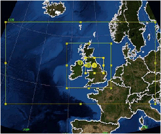
The majority of the WRF runs done in this project used the ‘Great North Run’ (GNR) configuration, chosen to be representative of the WRF-related work done by the UK community on HECToR . This configuration is shown in figure 1 and consists of three, nested domains with two-way feedback between them. It is designed to provide a ‘Weather Forecast’ for the north of England which is thus covered by a small domain of high-resolution (1 Km). The large but coarse outer region is designed to capture the behaviour of the atmosphere over the north Atlantic. It is rectangular rather than square since the regions to the north and south of it will have limited effect on what happens in the inner-most domain. This configuration is used by the National Centre for Atmospheric Science (NCAS), UK, as both a teaching tool and for use with scientific field campaigns being carried out in the UK.
The sizes of the three domains are given in table 1 in terms of numbers of grid points. These extents have implications for the scaling behaviour of WRF when running this configuration. Unless stated otherwise, all of the results presented in this document were obtained using the GNR configuration.
Number of grid points Domain East-West North-South Total 1 356 196 69176 2 319 322 102718 3 391 328 127600
Table 1: Domain sizes for the Great North Run configuration.
When measuring the performance of WRF we have used the mean time taken to integrate the whole model forwards in time by one time step. Typically, the mean value was calculated from three separate runs of 10 minutes of model time. This quantity explicitly excludes any time spent doing I/O.
Two versions of WRF version 3.1.1 have been installed on in /home/n02/n02/wrf/bin on HECToR:
Both of these have been built to include Parallel netCDF (version 1.1.1) functionality and with large (netCDF) file support. To improve performance when running nested models the compile-time switch ‘SGIALTIX’ was also enabled for these builds (see section 5.1).
In this section we examine the compute performance of WRF and look at strategies for improving it.
WRF is supplied with its own, interactive ‘configure’ script which seeks to identify the platform and offer appropriate options. On HECToR which has the Portland Group (PGI), Pathscale (PS), Gnu and Cray compiler suites installed, this results in approximately 20 different ways of building WRF. However, the relatively-young Cray compiler was unable to build WRF and therefore was not an option for this project. At the time of writing, the default compiler versions on HECToR are 3.2, 9.0.4 and 4.4.2 for the PS, PGI and Gnu F90 compilers, respectively.
The performance of WRF when compiled in distributed-memory (dm) mode (i.e. using the MPI library for parallelisation) with the three remaining options was compared and the results are summarised in figure 2. It is clear that the Gnu compiler is unable to match the performance achieved by either of the commercial compilers. Consequently, it was not used for the remainder of the project. The PS-compiled binary failed with a segmentation error during startup on all processing element (PE) counts tried. The default flags provided by the configure script (-O3 -OPT:Fast) were therefore edited until a stable version was obtained: -OPT:Fast was replaced with its lower-level equivalents (-OPT:ro=2:Olimit=0:div_split=ON:alias=typed) and these removed one by one. The final set of flags was -O3 -OPT:ro=1:Olimit=0:div_split=ON:alias=typed where ro=1 reduces the level of optimisations that affect round-off compared to ro=2.
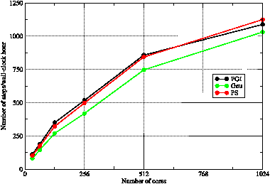
Figure 2: The performance of WRF when built ‘out of the box’ in distributed-memory mode with the Portland Group (PGI), Pathscale (PS) and Gnu compilers. (Note that the flags for the PS compiler had to be adjusted, as described in the text.)
When using the default flags supplied by the WRF configure script (with the correction for the PS flags described above) the performance achieved by the PS- and PGI-compiled binaries is very similar (figure 2). We now experiment to see what performance improvements may be achieved by tuning these flags. The settings produced by the configure script for the PGI compiler include a set of commented-out flags that cause more extensive optimisation to be performed, at the risk of altering the results produced by the code. These flags were used as the basis for seeking to improve the performance of WRF.
For the PGI compiler, it was found hard to improve upon the performance achieved by the optimising flags suggested by the configure script (but left commented-out by default). These flags are: -O3 -fastsse -Mvect=noaltcode -Msmartalloc -Mprefetch=distance:8 -Mfprel, where:
Experiments were performed with profile-guided optimisation and inter-procedural optimisation. The former did not significantly alter the performance of the binary but the latter (with -Mipa=fast) did improve things slightly at the cost of significantly increasing the compilation time. With the upgrade of HECToR to Phase IIa and the move from WRF 3.0.1.1 to 3.1.1 this slight improvement with the use of IPA disappeared and thus it is not included in the final set of flags.
The starting point for improving the set of optimising flags for the PS compiler was the set specified for PGI, converted to the PS equivalents. Again, varying extents of inter-procedural optimisation were tried but these all caused the compiler to crash with an ‘internal compiler error.’ The best set of flags for the PS compiler was found to be: -O3 -OPT:Ofast:ro=1:malloc_algorithm=1:early_intrinsics=ON -LNO:prefetch_ahead=8:full_unroll=10.
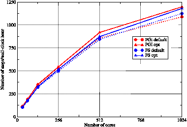
Figure 3: The performance of WRF when built in distributed-memory mode with the Portland Group and Pathscale compilers. Results for each compiler with the default set of flags (circles) are compared with the optimum sets of flags found in this work (triangles). Each symbol represents the mean result from three separate runs. Lines are guides to the eye.
A comparison of the performance of WRF when compiled with the default and optimised sets of compiler flags is shown in figure 3. This shows that the new set of flags for the PGI compiler has improved the performance of WRF by approximately 10% compared to that obtained with the default PGI flags. This is slightly greater than the equivalent improvement obtained with the PS compiler and consequently, the PGI-compiled binary performs best for all core counts although the differences at low and high core counts are small.
Since a compiler’s optimization of a code can alter the results it produces, it is essential to check that the optimized build of WRF gives results consistent with those compiled with lower optimization levels and/or with different compilers. These checks were performed by comparing the surface-pressure and surface-temperature fields produced by binaries compiled with different compilers and differing degrees of optimization. In particular, checks were performed between results from the most optimized binaries and those compiled with flags that force the compiler to only use math operations that are IEEE compliant.
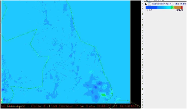
Figure 4: Differences between the ‘Temperature at 2m’ fields for the inner GNR domain produced by two different builds of WRF doing a six-hour simulation.
Results were compared using the Integrated Data Viewer (IDV) [5] with its ability to display the difference between two fields. An example of the small differences typically found is shown in figure 4 which displays the temperature at an elevation of two metres across the inner-most domain (number three) of the GNR configuration. Note the scale at the top-right of the image which shows that all differences are of the order of 0.1 Kelvin.
WRF was built in mixed-mode (MPI and OpenMP) with both the PGI and PS compilers. For version 3.0.1.1 of WRF it was found that the resulting PGI-compiled binary was some 10% slower than that produced by the PS compiler. On moving to version 3.1.1 of WRF, we were unable to get a working mixed-mode binary from the PGI compiler. However, given the performance difference for the previous version of WRF we considered it reasonable to consider just the PS results.
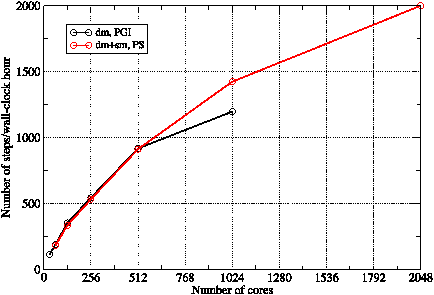
Figure 5: Comparison of the performance of (the PGI-compiled) dm-mode WRF with that of (the PS-compiled) dm+sm-mode WRF.
Figure 5 compares the performance of the PGI, dm-mode and PS, mixed-mode builds of WRF. The mixed-mode version was run with a single MPI process and four OpenMP threads per compute node. Below 512 cores, the mixed-mode binary is slightly slower than the pure MPI version. However, on larger core counts where communication overheads increase, the mixed-mode binary is significantly faster, presumably due to its reduction of the MPI communication between cores.
Note also that while attempting to run the GNR configuration on 2048 MPI PEs causes failure due to over-decomposition of the model domain, it is possible to run the mixed-mode binary on up to 4096 cores since we have four OpenMP threads per MPI process. (The 4096-core result of 2198 steps/hour is not plotted in figure 5 to allow better comparison with the dm-mode curve.)
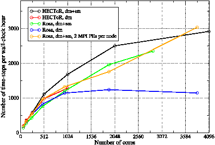
Figure 6: The performance of WRF running the GNR configuration on the HECToR and Rosa machines. The dm-mode binary was built with the PGI compiler and the dm+sm-mode binary with the PS compiler. Compute nodes were fully occupied for these jobs.
These results indicate that the mixed-mode version of WRF is very well suited to the increasingly fat nodes of current MPP machines. This is borne out by its performance on Monte Rosa which has 12 cores per node compared to HECToR’s four. The performance obtained from WRF running the GNR configuration on Rosa is shown in figure 6. Comparing the blue and green curves, we see that, as on HECToR , the performance of the dm+sm-mode binary does not exceed that of the dm-mode binary until the number of cores exceeds 1024. At this point the dm-mode binary ceases to give any useful performance improvement as the number of cores is increased.
Figure 6 also contains the equivalent results obtained on HECToR . These show that both the dm- and dm+sm-mode WRF binaries perform considerably better on HECToR than do their counterparts on Rosa. The only exception to this is the dm+sm-mode binary when run with two MPI processes per compute node (i.e. one per socket) on Rosa. This gives the best scaling performance of any option on either machine and does eventually exceed the performance of the dm+sm-mode binary on HECToR . What is clear from figure 6 is that the dm+sm-mode binary scales very much better than the dm-mode version on this architecture.
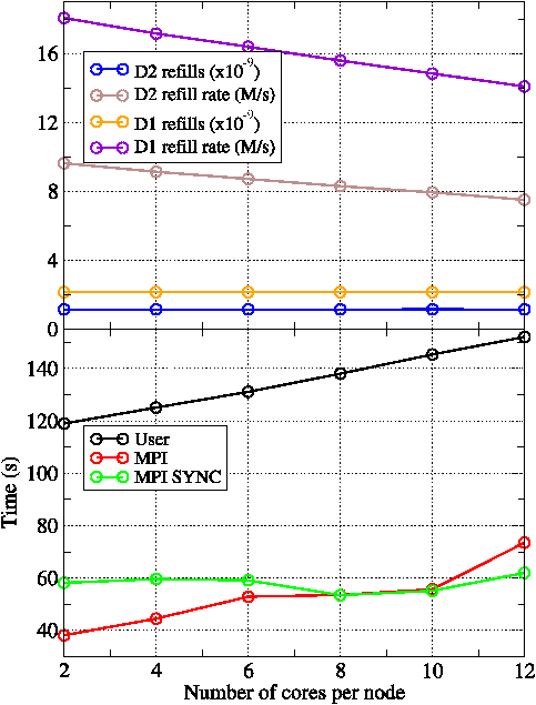
Figure 7: Break-down of the performance of dm-mode WRF on Rosa when the compute nodes are systematically under-populated. The upper plot shows cache-related performance for the level-1 and level-2 data caches (D1 and D2, respectively) for the user part of the code. The bottom plot shows how the time spent in the user and MPI parts of the WRF code varies with node population. All runs were on 480 PEs on Rosa.
That WRF performs better on HECToR than it does on Rosa is due to the high demand it places on memory bandwidth. This is demonstrated by the results in figure 7 which compares the performance of WRF running in dm-mode with 480 PEs on fully occupied nodes (i.e. with 12 cores per node [cpn]) to that obtained when the nodes are de-populated. The lower plot in figure 7 shows that the time spent by WRF in user and MPI code decreases by approximately equal amounts as the number of cpn is reduced from 12 to four. The time spent waiting at a barrier before any global MPI operation (largely due to load imbalance) is labelled as MPI SYNC and can be seen to remain roughly unchanged as the node population is varied. The reduction in the time spent in MPI is to be expected since reducing the number of processes running on a node will reduce the amount of data that must be sent and received over the interconnect, alleviating network contention.
The upper plot in figure 7 shows some hardware performance-counter results for cache usage which shed some light on the reduction in the time spent in user code as nodes are under-populated. Of particular importance is the increase in the rate of the fills of the level-1 data cache (D1) while the actual number of fills remains unchanged as the cpn is reduced. The fact that D1 is receiving data more quickly means that the compute cores will spend less time waiting for data from main memory. Note that neither the D1 nor D2 refill rates in figure 7 show any sign of levelling-off as the number of cpn is decreased, indicating that retrieving data from main memory remains the bottleneck.
WRF was written with OpenMP and OpenMP-MPI compilation in mind which has implications for the way in which it decomposes the model domain. When running in distributed-memory (‘dm’) mode, the model domain is decomposed into as many rectangular ‘patches’ as there are PEs (i.e. MPI processes) and each patch assigned to a PE. When running in mixed-mode (‘sm+dm’) those patches are further decomposed into ‘tiles’ which are then shared amongst the available OpenMP threads, see figure 8 for an illustration.
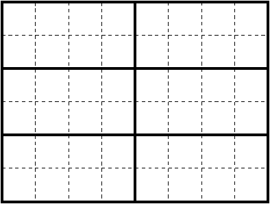
Figure 8: Illustration of a domain decomposition within WRF suitable for a mixed-mode job with six MPI processes, each with eight OpenMP threads. Patches are drawn with bold, solid lines and tiles with dashed lines.
Although this decomposition is generated automatically by WRF, the user can manually specify both the height/width of the grid of patches as well as the number of tiles per patch, even when no OpenMP is being used. (In this case, the single MPI process loops over the tiles at a high level within the code structure.) The effect of the choice of domain decomposition is investigated in section 5.2. Here we look at using the number of tiles/patch to tune the size of the arrays within the computation in order to make more efficient use of the cache architecture of the AMD processor.
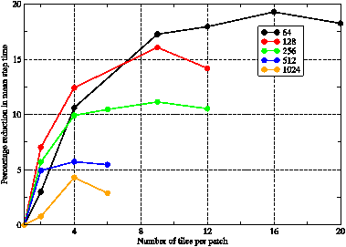
Figure 9: The percentage reduction in the mean wall-clock time taken to step the model as a function of the number of tiles used per patch. Results are shown for a variety of PE counts for the GNR configuration. Lines are guides to the eye.
Figure 9 shows the effect on the performance of WRF built in dm mode when the number of tiles per patch is increased. As one would expect, the use of tiling has the greatest effect on the lower PE counts when the patches and thus array extents are at their largest and therefore do not fit into cache. So we see that using 16 tiles/patch on a 64-PE job achieves a speed-up of almost 20% whilst the best achieved for the 1024-PE job is approximately 5% with just four tiles/patch.
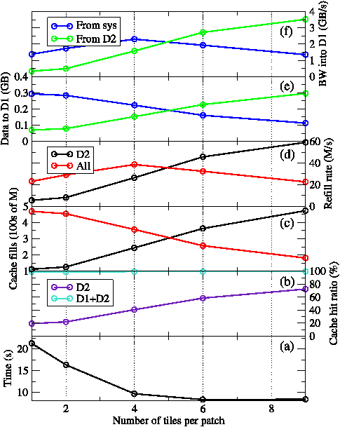
Figure 10: Performance data for the level-1 and -2 data caches for the horizontal_diffusion_s routine as the number of tiles per patch is increased. The bottom plot shows the total exclusive time spent in horizontal_diffusion_s during a run. Lines are guides to the eye.
Since the number of tiles per patch provides a straightforward way of varying array dimensions, it is interesting to see whether the resulting performance variation can be correlated with data from the hardware performance counters (HWPCs). We chose to study the performance of a single routine, horizontal_diffusion_s, since profiling showed that this is the most significant of the non-initialisation routines and that its performance is sensitive to the number of tiles/patch. WRF was run on 128 MPI PEs with CrayPat used to collect HWPCs related to cache accesses. The results relating to the level-1 and level-2 data caches (D1 and D2 for short) are shown in figure 10.
Plot (a) in figure 10 shows that the time spent in horizontal_diffusion_s reduces most significantly when the number of tiles/patch is increased from one to four. Looking at plots (e) and (f) it is clear that the number of cache fills from main memory drops as they are replaced by loads from D2. This reduces contention (since all four cores must access main memory over the same bus) and thus improves the rate at which such fills occur.
The AMD Barcelona chip has three levels of on-chip cache. The first two levels are private to each of the four cores while the third is shared between them. The level-1 (L1) cache has the lowest latency and is 64KB in size, level-2 (L2) is 512KB and the shared, level-3 (L3) cache is 2MB. L2 acts as a ‘victim cache’ for L1; when data must be evicted from L1 to make room for new data fetched from main memory, it is moved to L2. Similarly, L3 acts as a victim cache for L2.
It seems therefore that as the tile size is reduced, data that has previously been loaded from main memory to L1 is increasingly found to be still in L2 when it is next needed. This can be seen in plot (b) of figure 10 where the hit ratio (the % of requests for data that can be satisfied) for D2 increases from just 20% when a single tile is used up to 70+% when nine tiles are used. This is reflected in plot (e) where we see that the amount of data loaded into D1 from D2 (as opposed to from system memory) steadily increases as the number of tiles/patch is increased. Note that the hit ratio for D1 remains virtually unchanged throughout.
WRF was profiled extensively throughout the project using the Cray Performance Analysis Toolkit (CrayPat). An initial profile of a short WRF simulation (15 minutes) revealed that routine MODULE_MP_THOMPSON::QR_ACR_QS was accounting for approximately 40% of the wallclock time. However, examining the call tree using the Apprentice2 tool revealed that this routine is only called by thompson_init() which itself is only called from module_physics_init(). This routine is called as part of domain initialisation which only occurs at the beginning of a run.
Thus, the run time of the short simulation is dominated by initialisation. This must be allowed for when looking at timings and, ideally, removed from any profiling data. The simplest way of achieving the latter was found to be via CrayPat’s Automatic Profile Analysis (APA) functionality. Running pat_build with the “-O apa” flag generates a binary suitable for a sampling experiment. Since that is the default, simply running the new binary as usual produces a *.xf file which may be processed by the pat_report tool. As well as producing a text-based report, this creates a *.apa file containing a suggested configuration for instrumenting the binary for a tracing experiment. This file is plain text and is straightforward to edit allowing us to instruct CrayPat not to instrument any routines that we have identified as being only involved in initialisation.
Once the *.apa file has been tweaked as desired, a new binary instrumented for tracing may be generated by running:
pat_build -O <apa_filename>.
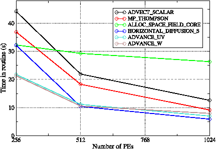
Figure 11: The time spent in the six most significant subroutines as the number of PEs is increased for WRF running a 40-minute simulation in dm-mode.
Once initialisation is accounted for, WRF’s profile is rather ‘flat’ with no one routine accounting for more than 4% of the total run time (for the GNR configuration on 256 PEs). This means there are no obvious candidates for actual code optimization.
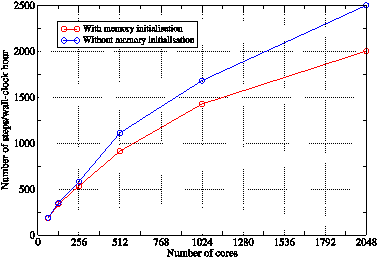
Figure 12: The effect on the performance of the mixed-mode binary when memory initialisation is removed from the ALLOC_SPACE_FIELD_CORE() routine. Lines are guides to the eye.
Figure 11 shows the scaling of the most significant routines as the number of PEs is increased from 256 to 1024. From this we see that all of the physics-based routines are scaling well but that ALLOC_SPACE_FIELD_CORE() is not. This is surprising given that all this routine does is allocate and then zero the memory required for interpolating data from one domain onto another. Closer examination of the profiling data showed that it was the memory initialisation that was not scaling, despite the fact that the amount of memory that each PE has to deal with should decrease as the number of PEs increases. The code authors suggested that the memory initialisation might not actually be required and supplied a compile-time option for turning it off (‘-DSGIALTIX’). Tests proved that the same answers were obtained when no memory initialisation was performed and that signifcant performance gains were achieved on higher core counts — see figure 12.
Given a number of PEs, n, on which to execute in dm mode WRF will, by default, select a factorisation nx . ny = n where nx and ny are as close as possible to √n. Here, nx and ny are the horizontal and vertical dimensions of the processor grid on which the domain is decomposed. The choice of this decomposition can affect the performance of the simulation since it changes the dimensions of the rectangular patches (and hence of the arrays) that each PE works on and also changes the length of the boundaries across which PEs must exchange halo data. Users may explicitly select a decomposition by setting the nproc_x and nproc_y fields in the input namelist file.
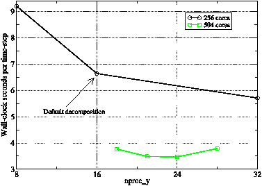
Figure 13: The variation in performance of WRF running the GNR configuration on 256 and 504 PEs as the x-y decomposition of the PE grid is varied. Lines are guides to the eye.
Predicting the effect on performance is complex but it is straightforward to run a few experiments and select the best domain decomposition for the model to be run. Figure 13 shows the results of doing this for the GNR configuration on 256 and 504 PEs on HECToR. Although the number of factorisations of 256 is limited, we can still find a case (8 × 32) that improves on the performance of the default decomposition by approximately 10%. On 504 PEs where the patches are much smaller, the effects are much less dramatic. This suggests that changing the shape of the patches affects compute speed more than it does the rate of halo exchanges.
In all that we have discussed so far, the benchmarking runs have been configured such that history data is not written out to file. However, this is unrealistic since the history data is actually the primary product of any scientifically-meaningful job. In this section we look at ways of mitigating the effect of outputting this data on the performance of WRF.
Thanks to its well-defined I/O API, WRF has several different implementations of its ‘I/O layer.’ In this work we have used two, netCDF-based implementations due to the popularity of that format in the environmental-science community: the default, serial netCDF layer and the layer built upon the pNetCDF library; a version that supports parallel I/O [4]. We have used version 3.6.2 of the netCDF library in this work.
On HECToR , the netCDF library is available as a module while the pNetCDF library used in some of the tests was built as part of this work. A netCDF file is created by WRF to contain the history for each domain in the model. Therefore, the GNR configuration produces three netCDF history files with the largest being that for domain 3 since that contains the most grid points (table 1). A single frame of history data is 1.63 GB for the GNR configuration.
The default approach to outputting a distributed array in WRF is to gather all of the data onto the master PE using a call to MPI_Gatherv, reconstruct the array and then write it to disk using the standard, serial netCDF library. Finally, the number of bytes written to disk is broadcast back to all PEs which means that all PEs block until the master has completed the write. The time taken to do all of this for each domain is written to standard output and it is this figure that has been used in the work here. Since it includes the time taken by the call to MPI_Gatherv, it is not strictly the time taken to write the data to disk but it is the amount of wall-clock time ‘lost’ due to doing the output.
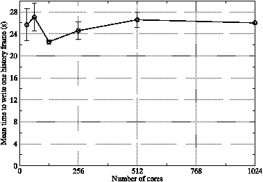
Figure 14: The mean time taken to write a single history frame for the GNR configuration as a function of job core count. Values represent the mean of at least four separate frame outputs and error bars show the associated standard error.
Figure 14 shows that the time taken to write a single frame of history for the GNR configuration is approximately 26 seconds and is largely independent of the number of cores used by the simulation over the range displayed (32–1024). On 1024 cores with the best-performing wrf binary, it takes 2.14 wall-clock seconds to integrate the model forward in time by one time step. Since the model time-step here is 18 seconds, this means that it takes 428 wall-clock seconds to simulate one model hour. The time taken to write one history frame is 6.1 percent of this, meaning that outputting the history every model hour will add six percent to the job time. Given the dependence of the method on MPI_Gatherv and the absence of any scaling in figure 14, this percentage will only increase on higher PE counts/larger model domains and we look at strategies for coping with this in the following sections.
The Cray XT series makes use of the Lustre distributed, parallel file-system which has hardware support for doing parallel I/O. HECToR is configured with 72 Object Storage Targets (OSTs; effectively the disks where the data resides) and large files may be striped across these to improve performance.
Using CrayPat to examine the I/O performance of WRF revealed that writes to disk are generally done four MB at a time. Since the default I/O scheme in WRF uses a single processor to write to the (large) history file for each domain, the Cray rule of thumb (from training course material) of using one OST per MB of a file would indicate that four OSTs will be optimal. However, although the amount of data written for a frame is of the order of 0.5 GB for each GNR domain, this data is made up of many different variables, all of which are written separately. In fact, instrumenting the source code revealed that a write of a single frame for one GNR domain involved 160 calls to the netCDF write routine. This is clearly not optimal for achieving good I/O performance unless the netCDF library performs some sort of caching.
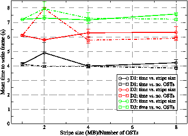
Figure 15: The mean time taken during calls to the netCDF library to write a single history frame for the GNR configuration as functions of stripe size and of number of OSTs. Values represent the mean of at least four separate frame outputs and error bars show the associated standard error.
In figure 15 we show the results obtained for the time spent in the WRF I/O-layer wrapper for the netCDF write operation (ext_ncd_write_field routine) as a function of both the stripe size and number of OSTs used for the output files. These results confirm that the write performance is unaffected by either the stripe size or the number of OSTs used, as we would expect if the individual writes are small. Note that obtaining consistent timings for this quantity proved very difficult since large variations were frequently seen. e.g. although the mean time to write domain 3 is typically seven seconds, times of 30 seconds were often seen and one write of the domain took 97 seconds. Presumably such exceptions are due to resource contention. These cases were excluded from the mean values shown in figure 15.
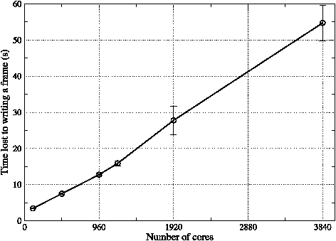
Figure 16: The time ‘lost’ to writing a single frame of history data as the number of cores used in the WRF job is increased. Each data point represents the mean value obtained from three separate runs on Rosa and error bars show the associated standard error. Lines are guides to the eye.
As mentioned earlier, WRF comes with an I/O layer implemented with pNetCDF — an extension of the netCDF library that supports parallel I/O. Unfortunately WRF is written such that when it is built to use this layer, every PE writes its part of the data to disk. On large PE counts, each of these writes is then for a relatively small amount of data and the large number of writers accessing a single file can cause contention. This is illustrated by the results (obtained on Rosa) shown in figure 16 where the time lost to writing out a single frame of history can be seen to increase almost linearly with the number of cores being used. Although it might be possible to improve this performance by tuning the number of OSTs being used (it was left at the default value of four), it is clear that this method will not scale to very high PE counts.
It appears therefore that, as implemented, the pNetCDF layer in WRF is best suited to the case where the amount of memory available to any individual PE is insufficient to permit the gathering of data to a single writer.
As described in section 6.1, in the default I/O layer all of the PEs must wait for the master PE to finish writing the history data to disk before proceeding with the computation. A useful optimisation therefore is to set aside one or more PEs for dealing exclusively with I/O. Once the ‘compute’ PEs have transmitted their data to these ‘IO servers’ they are free to continue with the calculation without waiting for the data to actually be written to disk. WRF contains such functionality with the user able to select how many PEs to dedicate to I/O at run time through the ‘namelist_quilt’ section of the input file. The IO servers themselves reconstruct the field to be to be written on the ‘root’ IO server which then writes it to disk using one of the serial WRF I/O layers (netCDF in this case).
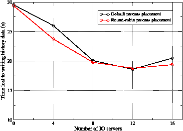
Figure 17: The mean time ‘lost’ by each of the compute nodes when writing a single history frame. WRF was run with 1024 compute PEs plus the specified number of IO servers.
We tested the performance of this functionality on HECToR for a job consisting of 1024 compute PEs and the results are shown in figure 17. Essentially, use of the IO servers reduces the time ‘lost’ by the compute PEs in writing a single frame of history from 30 to 19 seconds. The optimum number of IO servers in this particular case is 12 so that there are approximately 85 compute PEs per server.
With the introduction of IO servers, the bottleneck associated with doing I/O is no longer the actual sending of data to disk but is instead the gathering of data from the compute PEs onto the IO servers (the actual time spent writing remains unchanged but no longer delays the compute PEs). In the WRF code, each IO server is associated with a number of compute PEs and together these PEs are mapped into an MPI communicator. The gathering of data from the compute PEs onto the IO server is then implemented using an MPI_Gatherv across this communicator. WRF is implemented such that the last nIO PEs in MPI_COMM_WORLD are taken to be the IO servers and compute PEs are then associated with these IO servers in round-robin fashion.
By default, MPI tasks on the Cray XT are mapped to compute nodes in SMP style and consequently the WRF IO servers all end up packed together on a handful of nodes. This is not ideal given that all of the compute PEs must send their data to this group of IO servers – a great deal of network contention will result. The situation can be improved by specifying a custom mapping of MPI tasks to nodes and we have experimented with using this to distribute the IO servers evenly amongst the nodes.
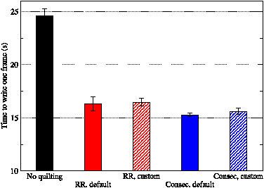
Figure 18: The effect of process placement (default or custom) and compute-PE to IO-server assignment (round-robin or consecutive) on the mean time ‘lost’ by the compute nodes when writing a single history frame. WRF was run with 128 compute PEs plus four IO servers on Rosa.
The round-robin association of compute PEs with IO servers also has performance consequences given the current trend in MPP machines towards ‘fat’ nodes; the number of cores per compute node is steadily increasing. On HECToR it is currently four but is set to increase to 24 in June 2010. Cray’s Message-Passing Toolkit (MPT) is optimised for such an architecture. For example, intra-node MPI communication is done via shared memory so the associated data never has to travel via the compute node interconnect. It therefore seems sensible to capitalize on this by associating consecutive compute PEs with an IO server with the result that, in general, all of the compute PEs on a single compute node will be sending their data to the same IO server giving MPT the opportunity to aggregate the communications.
Figure 18 shows the effects on I/O performance of changing the process placement and compute-PE to IO-server assignment. It is clear from these results that for a job of this modest size, the choice of process placement and mapping has very little effect on the time taken to write a frame of history. That said, changing the assignment of compute-PEs to IO-servers from round-robin to consecutive does have a small, beneficial effect.
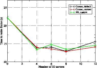
Figure 19: The mean time ‘lost’ by the compute nodes when writing a single history frame for 516 compute PEs on Rosa.
In order to test these conclusions we performed further runs on a more realistic, larger PE count of 516 on Rosa and the results are shown in figure 19. Comparing the red and black curves, we see that specifying a custom process placement does have a beneficial effect when six or 12 IO servers are used. This is possibly because, with the default process placement, these cases would consist of having one or two sockets occupied solely by IO servers. Moving on to the assignment of compute PEs to IO servers, the green and red curves show that assigning consecutive blocks of compute PEs to IO servers gives, in general, slightly better performance. However, as with the smaller test job, the variations in performance given by these considerations are small compared with the performance improvement gained by having any IO servers at all.
Experience with increasing the vertical resolution of a model has indicated that the run-time is proportional to the number of vertical layers in the model grid. However, the pressing concerns of HECToR’s I/O performance and the implications of the impending upgrade to Phase IIb with its much fatter compute nodes meant that it was agreed to devote effort to those areas at the expense of thoroughly investigating the issues surrounding vertical resolution.
We have considered various aspects of the performance of the WRF model on a Cray XT4 with four cores per node and an XT5 with 12 cores per node. Building WRF in mixed (MPI+OpenMP) mode was found to give the best absolute and parallel-scaling performance and in fact proved to be essential in trying to achieve the same performance on the fatter nodes of the XT5 as was obtained on the XT4.
The memory-bandwidth aspects of the performance reduction seen on the XT5 system were investigated by systematically under-populating the nodes used by a job and collecting hardware performance counter data. This showed that memory bandwidth remains a bottleneck even when nodes are populated with just one task per socket. Unfortunately, the current trend towards chips with increasing numbers of cores will only exacerbate this problem for all codes that are memory-bandwidth limited.
When an application is up against the ‘memory wall’, it becomes even more important to ensure that it makes efficient use of on-chip cache. WRF makes use of OpenMP threads by further decomposing a PE’s patch of the model domain into tiles that are shared amongst them. This functionality is available even when WRF is not built with OpenMP support and therefore allows the user to tune the size of the arrays involved in the computation. We found that such tuning significantly improved the hit rate of the D2 cache (from 20 up to 70+%) and in so doing could improve WRF’s performance by ∼5% on 1024 PEs through to ∼20% on 64 PEs.
Ultimately, any environmental-science code must write results to disk and do so as quickly as possible. We have experimented with the various WRF I/O and Lustre configuration options. Improving the performance of the writes themselves proved unsuccessful since they consist of a large number of small writes, one for each variable. It may be productive to experiment with the caching used in the netCDF library in order to tackle this. Of the WRF I/O options, the ‘I/O quilting’ functionality proved the most successful. This hides the actual time taken to write the data to disk by using dedicated ‘IO server’ PEs. The time-limiting step is then the gathering (via MPI_Gatherv) of data from the compute PEs to the IO servers. Experiments in altering the way in which compute PEs are assigned to IO servers and in the mapping of PEs to the nodes of the machine achieved only small improvements compared to the improvement obtained by introducing any IO servers. It is likely that the performance of the data-gathering stage could be improved through using MPI point-to-point communications rather than the global gathers that the current implementation performs. We plan to experiment with this in the future.
A significant limitation of the I/O-quilting functionality, as currently implemented, is the fact that ultimately, the data is still gathered onto a single PE for writing to disk. This fails to make best use of the parallel file-system on HECToR. More significantly, this method will frequently be unusable as increasing model sizes combined with reductions in the memory available per core will mean that whole fields will not fit into the memory available to a single core. Removing this limitation will require re-coding the I/O-quilting functionality so that the IO servers do parallel I/O.
This work has been funded by the Engineering and Physical Sciences Research Council, UK, through the dCSE support programme administered by NAG, UK. We are also grateful for the access we were granted to Monte Rosa, a Cray XT5, hosted at the Swiss National Supercomputing Centre (CSCS).
Invaluable problem-solving assistance was provided by one of the code authors, John Michalakes of NCAR.
This document was translated from LATEX by HEVEA.